Quality Control in CNC Machining: How Tolerances, Surface Finish, and Geometry Are Verified
 Precision is the foundation of CNC machining, especially in aerospace, automotive, medical devices, and electronics industries. However, the ability to produce a complex part is only part of the equation—ensuring that every component meets exact specifications through rigorous quality control is just as critical.
This blog explores how quality control is implemented in CNC machining, focusing on three key aspects: dimensional tolerances, surface finish, and geometric integrity. We discuss industry standards, inspection tools, and how manufacturers like Neway ensure that custom parts meet or exceed customer expectations.
Why Quality Control Is Critical in CNC Machining
Even minor deviations in a CNC-machined part can lead to functional failure, poor fit, or safety risks. Precision tolerances, consistent finishes, and geometric conformity are essential to ensure:
Seamless assembly with mating components
Consistent product performance and safety
Compliance with industry standards such as ISO 2768, ASME Y14.5, and DIN ISO 286
Reduced rework and warranty claims
Certification for regulated industries like aerospace and medical
At Neway, every part undergoes a structured quality control process from raw material traceability to final inspection. We provide precision CNC machining services with full inspection reports, CMM measurements, and first article documentation upon request.
Dimensional Tolerances: Verifying Accuracy to Microns
Tolerances define the allowable variation from a specified dimension. They are critical for fit, function, and interchangeability of parts, especially in assemblies where tight clearances or press fits are involved.
Common Tolerance Standards
ISO 2768-m and ISO 2768-f: For general machining; typical tolerances range from ±0.1 mm to ±0.05 mm depending on feature size
ASME Y14.5: Includes Geometric Dimensioning and Tolerancing (GD&T) for form, orientation, and position
DIN ISO 286: Tolerance fits for shaft and hole systems
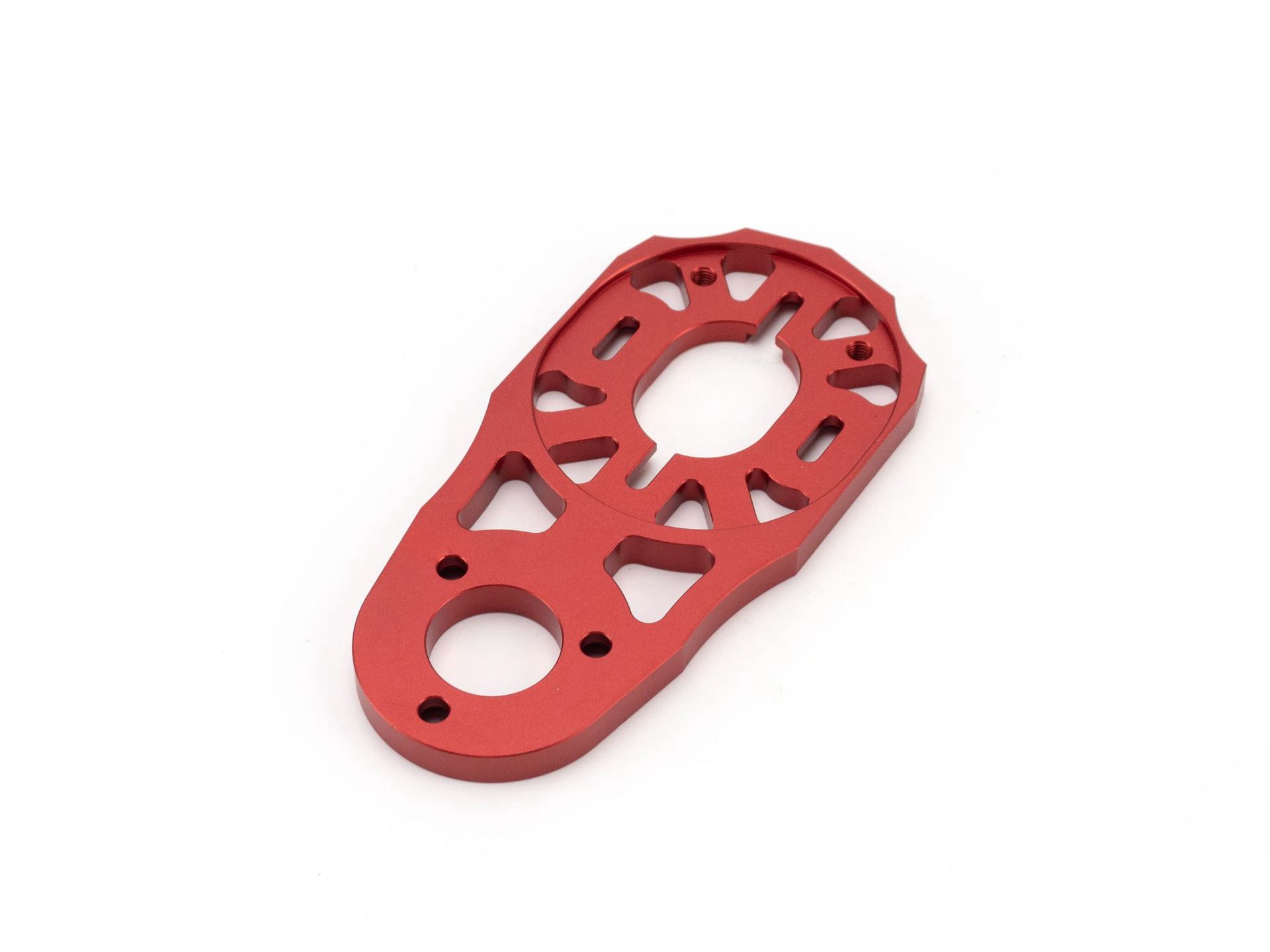
Custom tolerances down to ±0.01 mm for high-precision applications
Dimensional Inspection Tools
Digital calipers and micrometers: Measure external, internal, and depth dimensions with ±0.01 mm accuracy
Height gauges: Verify vertical features relative to a datum
Coordinate Measuring Machines (CMM): Deliver accuracy down to ±0.002 mm with programmable probe paths
Optical comparators: Project 2D profiles for dimensional comparison
Go/No-Go gauges: Allow fast validation of holes, shafts, and threads
Neway uses Zeiss and Hexagon CMMs in temperature-controlled environments to validate tolerances, particularly for parts in aerospace and medical device sectors.
Surface Finish: Measuring Quality Beyond Dimensions
Surface finish impacts more than just the appearance of a machined part. It affects mechanical performance in areas such as sealing, bearing contact, and fatigue life. Rough or inconsistent finishes may cause leaks, high friction, or early wear in critical components.
Surface Finish Standards
Surface roughness is most commonly measured as Ra (roughness average), which quantifies the average deviation from a mean line in micrometers or microinches.
Typical Ra values:
Ra 6.3 µm: Standard for as-machined surfaces
Ra 3.2 µm: Common finish for general-purpose functional parts
Ra 1.6 µm: Suitable for mating components and medium-precision assemblies
Ra 0.8 µm or lower: Required for sealing surfaces, medical parts, or high-performance components
Surface Inspection Methods
Contact profilometers: Use a diamond-tipped stylus to scan surface features along a defined trace
Optical profilometers: Non-contact systems using laser or interferometry to scan and analyze texture
Visual inspection with 10× magnification: Common for aesthetic finishes
Surface roughness comparators: Reference plates used in field inspection
At Neway, we can achieve surface finishes as fine as Ra 0.4 µm using high-speed end milling, electropolishing, or fine abrasive blasting. We also offer cosmetic treatments such as anodizing, powder coating, and brushing.
Geometric Accuracy: Ensuring Form and Orientation Integrity
Geometric tolerancing defines how features relate to each other in space. Unlike linear dimensions, these tolerances control flatness, straightness, parallelism, and location in three dimensions. They are essential for functional assemblies and complex components such as housings, pistons, and rotors.
Common Geometric Tolerances
Defined using GD&T symbols per ASME Y14.5 or ISO 1101:
Flatness: Limits deviation of a surface from a theoretical plane (e.g., ≤0.03 mm across 100 mm)
Parallelism: Controls how uniformly two surfaces or features align
Perpendicularity: Ensures accurate 90° angles for precision mating
Cylindricity: Controls the roundness and straightness of cylindrical surfaces
True position: Specifies allowable variation from theoretical center locations
Geometric Inspection Tools
CMM probing with point cloud mapping
Dial indicators and surface plates for flatness and parallelism checks
Roundness testers and runout gauges
Optical coordinate measuring systems for complex part geometries
For example, a critical aerospace bushing may require position tolerance of 0.02 mm and perpendicularity of 0.01 mm relative to the mounting flange—measured using 3D CMM inspection and cross-verified with alignment fixtures.
Material and Traceability Verification
Dimensional accuracy means little without assurance of material integrity. Traceability ensures that the correct material is used, meets standards, and is properly documented.
Key elements include:
Material Test Reports (MTRs) compliant with EN 10204 3.1
Positive Material Identification (PMI) for critical alloys
Heat lot tracking for serialized or regulated components
Hardness testing per ASTM E18 or ISO 6508
Certification to RoHS, REACH, or FDA when required
Neway provides full material and inspection documentation as part of its one-stop service for regulated industries including energy, medical, and aerospace.
In-Process vs Final Inspection
Effective quality control is not a one-time activity. It is integrated into every manufacturing stage to reduce scrap, minimize rework, and ensure conformity.
In-process inspection: Performed after each critical operation (e.g., rough milling, drilling)
Tool life and offset monitoring: Ensures tool wear does not cause gradual drift
SPC (Statistical Process Control): Used in batch runs to identify trends and deviations
Final inspection: Includes full CMM validation, surface checks, and dimensional reports
Neway implements quality control systems per ISO 9001 and performs FAI (First Article Inspection) per AS9102 on request for aerospace-grade projects.
Conclusion
Quality control in CNC machining involves precise tolerances measurement, surface finish verification, and geometric conformity assessment. By combining calibrated inspection tools, international standards, and rigorous documentation, manufacturers ensure every part meets its intended function and fits perfectly in the final assembly.
At Neway, we integrate advanced inspection technology, trained quality engineers, and traceable process control to guarantee the performance of your CNC machined components. Whether you're developing a prototype or scaling to production, our commitment to quality ensures every part is right the first time.
Frequently Asked Questions (FAQs)
What is the standard tolerance for CNC machined parts?
How is surface roughness measured and specified?
What inspection tools are used for verifying tight tolerances?
How do manufacturers control geometry in complex CNC parts?
Can Neway provide full CMM inspection reports and FAIR documentation?