Understanding Machining Tolerances: What Buyers Must Know Before Ordering CNC Parts
 When ordering custom CNC machined parts, understanding machining tolerances is crucial. Tolerances directly impact part fit, performance, cost, and lead time—especially in aerospace, medical, and automotive industries where precision is non-negotiable. This guide explains machining tolerances, their definition, and what buyers should consider when specifying them for CNC manufacturing.
What Are Machining Tolerances?
In CNC machining, a tolerance is the permissible variation in a part’s dimension from its nominal (or ideal) value. Because no manufacturing process can produce perfectly exact dimensions every time, tolerances set acceptable upper and lower limits for size and geometry.
For instance, a shaft with a specified diameter of Ø10.00 mm ±0.02 mm permits actual measurements between 9.98 mm and 10.02 mm. This tolerance range ensures the shaft fits securely into its mating bore without excessive looseness or tightness.
Tolerances are critical to ensuring components' interchangeability, functionality, and repeatability, especially when multiple parts are manufactured separately and later assembled.
Common Types of CNC Machining Tolerances
Machining tolerances are generally categorized into dimensional and geometric tolerances. Buyers should understand both when designing and specifying precision parts.
Dimensional tolerances:
Linear tolerances apply to length, width, and thickness features.
Diameter tolerances are common for shafts, pins, and holes.
Angular tolerances specify permissible deviation from specified angles.
Geometric Dimensioning & Tolerancing (GD&T):
Flatness controls surface straightness without reference to a datum.
Parallelism ensures two surfaces are equidistant across their lengths.
Cylindricity ensures uniform roundness and straightness of a cylindrical part.
True position defines allowable location variation for features like holes or slots.
Concentricity and runout manage rotational alignment for shafts or bores.
Neway supports full GD&T-compliant manufacturing with advanced inspection through precision CNC machining services for tight-tolerance applications in aerospace, robotics, and medical fields.
Standard Tolerance Grades in CNC Machining
Machining tolerances are often based on international standards such as ISO 2768 and ASME Y14.5. These standards define general tolerance classes for dimensions not explicitly toleranced in drawings.
According to ISO 2768-1, the following general tolerances apply to features between 0.5 mm and 30 mm:
Tolerance Class | Typical Linear Tolerance | Suitable Applications |
|---|---|---|
ISO 2768-f (Fine) | ±0.05 mm | Aerospace, optical devices |
ISO 2768-m (Medium) | ±0.10 mm | Automotive, mechanical assemblies |
ISO 2768-c (Coarse) | ±0.20 mm | Structural or non-critical parts |
Neway typically offers ±0.10 mm or better as a standard tolerance across most CNC machining services. We can achieve tolerances down to ±0.005 mm for ultra-precision applications with CMM-verified inspections.
How Tolerances Impact Cost and Lead Time
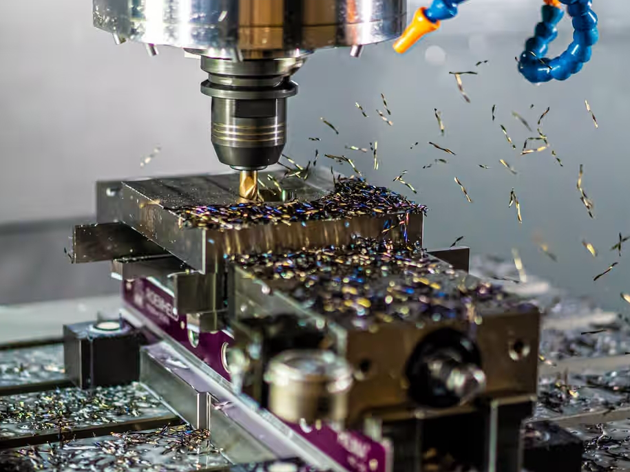
Tighter tolerances require more specialized tooling, reduced cutting speeds, and advanced inspection—all of which increase production time and cost. As tolerance tightens, the risk of part rejection also increases due to reduced margin for error.
For example:
A tolerance of ±0.10 mm may require basic tool paths and minimal inspection.
±0.05 mm necessitates precision machining and partial CMM checks.
±0.01 mm or tighter involves climate-controlled environments, high-end metrology, and specialized cutting tools.
Cost implications:
Machining ±0.10 mm features may cost 1.0× baseline
Machining ±0.05 mm features can cost 1.5–2.0×
Machining ±0.01 mm features often costs 3.0× or more
At Neway, our engineering team provides DFM consultation to help you select tolerances that align with both performance and budget goals.
When to Use Tight or Loose Tolerances
Tolerances should be based on the functional role of each dimension. Over-tolerancing leads to unnecessarily high manufacturing costs, while under-tolerancing may compromise assembly or performance.
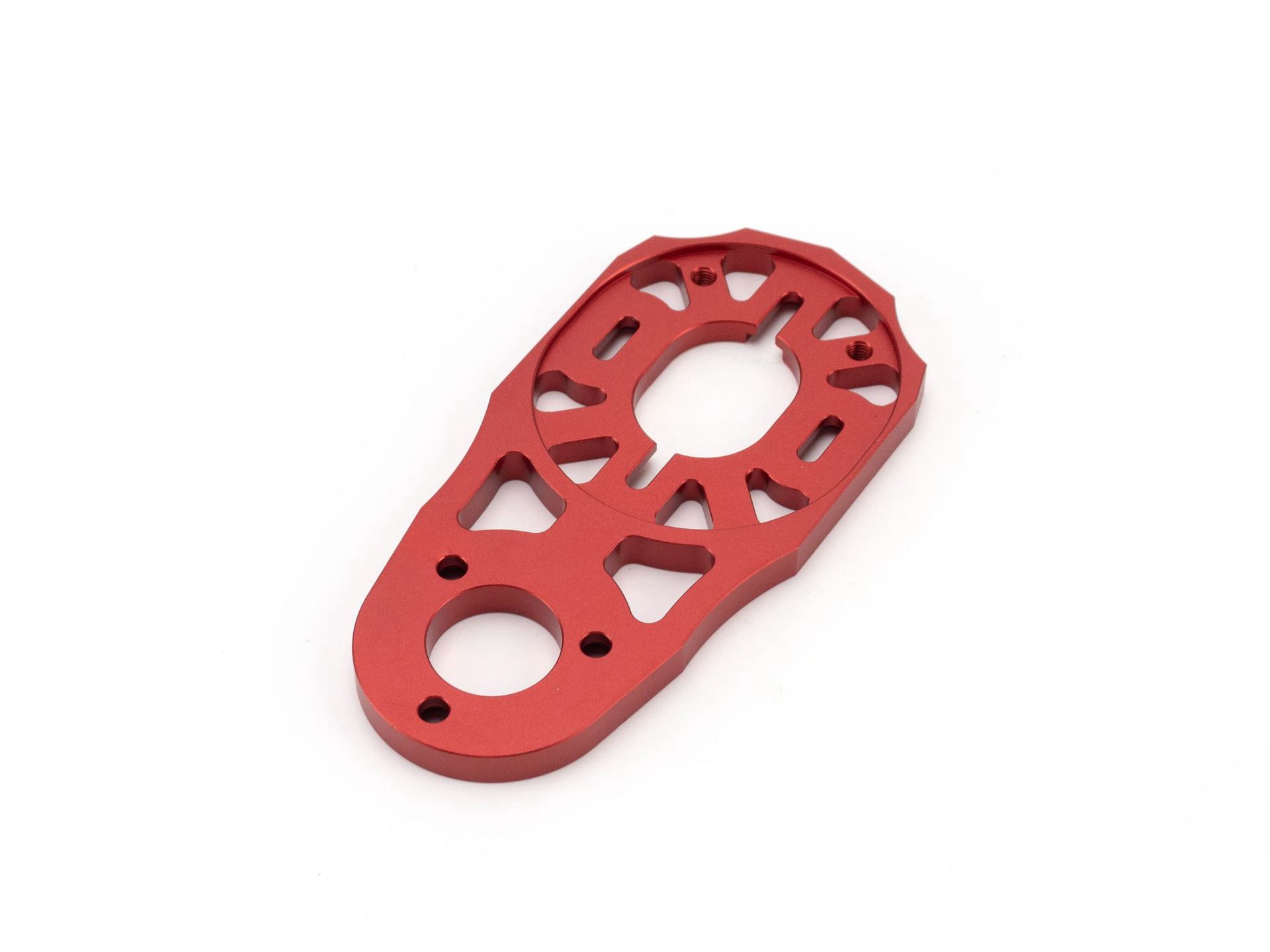
Use tight tolerances (±0.01–0.03 mm) for:
Press-fit shafts and bearing bores
Sealing surfaces for hydraulic systems
Medical instruments and surgical components
Aerospace brackets requiring precise alignment
Use standard or loose tolerances (±0.05–0.20 mm) for:
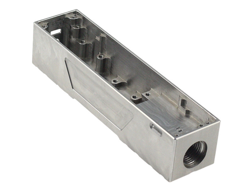
Cover plates or housings
Mounting flanges
Cosmetic components or non-mating features
Neway offers DFM support to review your drawings and recommend optimal tolerances based on intended use, mating components, and industry practices.
Inspection and Quality Control of Toleranced Features
Tight tolerances demand accurate and repeatable measurement techniques. Quality control at Neway includes the following equipment and methods:
Coordinate Measuring Machine (CMM): Accurate to ±2 µm for verifying GD&T and tight dimensions
Optical comparators: Project magnified part profiles for visual tolerance verification
Digital calipers and micrometers: Accurate to ±0.01 mm for routine inspection
Pin gauges and bore gauges: Used to check holes and internal features
Go/No-Go gauges: Cost-effective validation of critical limits
Neway supports full documentation, including material certification, inspection reports, and First Article Inspection (FAI) as required by customers in regulated industries.
How to Specify Tolerances on Your Drawings
To avoid ambiguity and rework, clearly communicating tolerance requirements on part drawings is essential. Here are recommended practices:
Specify general tolerance class (e.g., ISO 2768-m) in the title block
Add specific tolerances for critical dimensions directly next to the feature
Use proper GD&T symbols and datums for features requiring geometric control
Include surface finish requirements, especially for sealing or optical components
If you are submitting a STEP or IGES model without a 2D drawing, include a separate PDF with tolerance annotations or a general note such as “Unless specified: ±0.10 mm.”
Neway’s quoting team will contact you during the RFQ process if any tolerance conflicts or ambiguities are found, helping avoid costly delays.
How Neway Helps Optimize Tolerances
At Neway, we deliver custom CNC machining solutions across aluminum, stainless steel, titanium, copper, plastic, and ceramic materials. Our facilities have high-precision multi-axis machining, EDM machining, and in-house CMM inspection.
We help clients:
Review 2D/3D files to identify over-constrained tolerances
Suggest alternate fits (e.g., H7/g6) or general tolerance classes
Balance performance and cost for high- or low-volume production
Meet the strictest quality requirements with traceable documentation
Our experience across industries such as aerospace, medical, automation, and consumer electronics ensures that your tolerances align with your real-world application.
Conclusion
Understanding machining tolerances is key to successful part performance and cost efficiency. Buyers should define tolerances that match function, apply industry standards such as ISO 2768 and ASME Y14.5, and consult with their CNC partner for design optimization.
With Neway’s advanced machining capabilities, materials expertise, and precision inspection, we ensure your parts are manufactured to the exact specifications needed—no more, no less.
To get started, explore our CNC machining services or contact our engineering team for a free tolerance review today.
Frequently Asked Questions (FAQs)
What is the tightest machining tolerance Neway can achieve on custom CNC parts?
How do I know which dimensions on my part require tight tolerances?
Will tighter tolerances significantly increase the lead time for my project?
Can I request a tolerance review or optimization during the quoting process?
What inspection reports are included with precision CNC machined components?