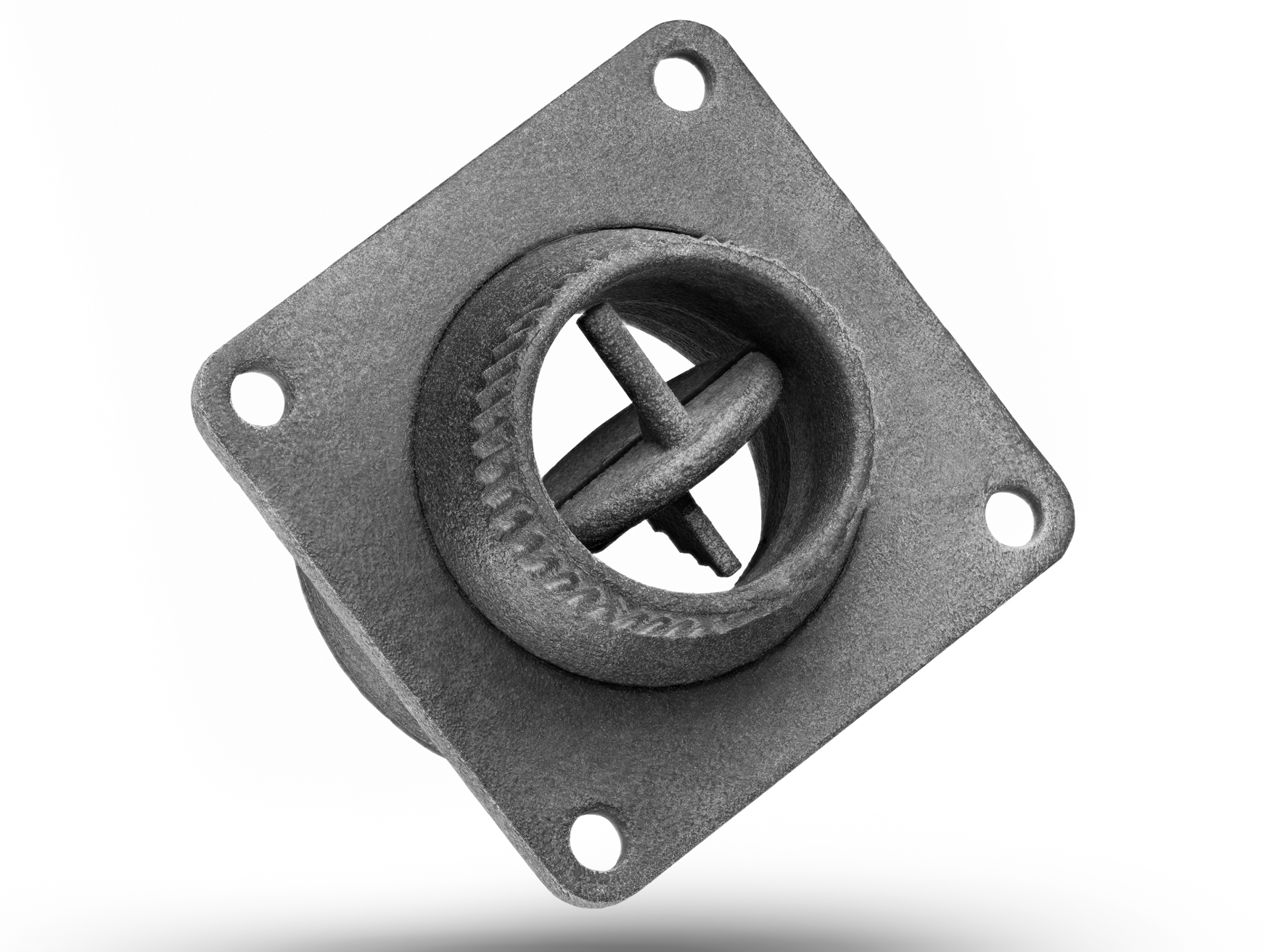
An Introduction to Multi Jet Fusion (MJF) 3D Printing
Introduction
Multi Jet Fusion (MJF) redefines industrial additive manufacturing by combining unprecedented speed, precision, and scalability. This powder-bed technology uses infrared energy and proprietary agents to fuse nylon-based materials layer-by-layer, producing end-use parts with mechanical properties rivaling traditional manufacturing. From aerospace brackets to medical devices, MJF eliminates tooling delays and enables complex geometries unachievable through CNC or injection molding.
At Neway, MJF powers our industrial 3D printing services, delivering functional prototypes and production-grade components in days. Backed by hybrid manufacturing expertise, we optimize MJF workflows for industries demanding speed-to-market and cost efficiency.
How MJF Works: Process Principles
The MJF process involves three core stages:
Powder Layering: A fine nylon (PA12) or composite powder layer is evenly spread across the build platform.
Inkjet Deposition: Precision print heads selectively apply fusing and detailing agents to the powder bed.
Infrared Fusion: High-powered infrared lamps melt the powdered material layer-by-layer, creating fully dense parts.
This process, rooted in Powder Bed Fusion (PBF) technology, ensures isotropic strength and eliminates weak layer bonds common in other AM methods.
Common MJF Materials
MJF 3D printing specializes in high-performance thermoplastics. Below are the key materials with validated Neway processing capabilities:
Material | Tensile Strength | HDT @ 0.45MPa | Key Properties | Common Applications |
|---|---|---|---|---|
48 MPa | 175°C | High strength, chemical resistance | Functional prototypes, housings | |
45 MPa | 160°C | Enhanced stiffness, dimensional stability | Automotive brackets, tooling | |
25 MPa | 80°C | Flexibility, shock absorption | Seals, grips, wearable devices | |
Flame-Retardant PA12 | 40 MPa | 170°C | UL94 V-0 certification, self-extinguishing | Electrical enclosures, aerospace |
Key Technical Features of MJF 3D Printing
Multi Jet Fusion (MJF) stands out in additive manufacturing with its unique combination of precision, efficiency, and material versatility. Below are the critical technical specifications validated through ASTM/ISO testing and real-world industrial applications:
Precision & Resolution
Layer Thickness: 80 microns (0.08 mm), enabling fine feature definition (e.g., 0.5 mm wall thickness).
Dimensional Accuracy: ±0.1% with a lower limit of ±0.2 mm (per ISO 2768 medium tolerance), surpassing SLS (±0.3 mm) and FDM (±0.5 mm).
Minimum Feature Size: 0.3 mm for holes and channels, ideal for fluidic systems or micro-textured surfaces.
Mechanical Performance
Isotropic Strength: Tensile strength uniformity across X/Y/Z axes (PA12: 48 MPa tensile, 2.5 GPa flexural modulus per ASTM D638/D790).
Thermal Stability: Heat deflection temperature (HDT) of 170°C for PA12 at 0.45 MPa (ASTM D648), suitable for under-hood automotive components.
Chemical Resistance: Resists oils, fuels, and weak acids (tested per ISO 175), outperforming ABS and PLA in harsh environments.
Production Efficiency
Build Speed: 5–10 mm/hour vertical print rate, completing a 300 × 220 × 200 mm build chamber in 6–12 hours.
Batch Scalability: Simultaneously produces 100+ discrete parts per cycle with nesting optimization (e.g., 400 dental aligners in one job).
Post-processing: 30% faster than SLS due to self-supporting powder bed; minimal manual intervention required.
Surface & Aesthetic Quality
As-Printed Roughness: Ra 10–15 μm (comparable to sand-cast metal), reducible to Ra 0.8 μm with vapor polishing.
Color Options: Gray (default), black (via dyeing), or custom Pantone-matched finishes using UV-resistant coatings.
Core Advantages Over Conventional Methods
Small-Batch Economics: MJF eliminates tooling costs, reducing per-part expenses by 40–60% vs. CNC machining for components with undercuts or internal channels.
Material Utilization: Achieves >95% powder reuse rate vs. CNC’s 60–80% material waste
Topology Optimization: Create lattice structures with 80% weight reduction while maintaining ISO 527-2 tensile strength (>48 MPa for PA12).
Assembly Consolidation: Replace multi-part assemblies with single MJF units, cutting automation system component counts by 70% (Case: Robotic end-effector integration).
Rapid Iteration: Transition from CAD to functional prototype in 8–24 hours (vs. 5–15 days for CNC toolpath programming).
Parallel Scaling: Simultaneously produce 100+ unique parts in a single build chamber, ideal for medical device trials.
Isotropic Properties: XYZ-axis tensile strength variation <5% (vs. 15–30% in FDM), critical for load-bearing industrial parts.
Chemical Resistance: PA12 maintains >90% elongation at break after 500hrs ASTM D543 chemical exposure, outperforming ABS/POM in oil & gas environments.
MJF vs. CNC vs. Injection Molding: Critical Parameter Comparison
Manufacturing Process | Lead Time | Surface Roughness | Geometric Complexity | Minimum Feature Size | Scalability |
|---|---|---|---|---|---|
MJF 3D Printing | 4–12 hours (No tooling, direct from CAD) | Ra 10–15 μm | ✅ Unrestricted - Internal channels - 0.3mm thin walls - Lattice structures | 0.3mm (Holes, pins, fine textures) | 1–10,000 units (Agile, no tooling cost) |
CNC Machining | 3–7 days (Programming + fixturing) | Ra 1.6–3.2 μm | ❌ Tool Access Limited - Min. 2.5mm tool diameter - 3–5 axis constraints | 0.5mm (Drill bits, end mills) | 10–500 units (High labor cost for large batches) |
Injection Molding | 4–8 weeks (Mold fabrication required) | Ra 0.4–0.8 μm | ❌ Draft Angles Required - No undercuts - Uniform wall thickness | 0.2mm (But requires complex mold texturing) | >10,000 units (Economies of scale) |
Industry-Specific MJF Applications
Aerospace: Satellite antenna brackets, UAV engine covers, missile shroud prototypes
Medical & Dental: Orthopedic surgery guides, dental invisible aligner molds, custom hearing aid housings
Automotive: Electric vehicle battery cooling plates, interior function button prototypes, hydrogen fuel cell bipolar plates
Energy: Oil and gas valve seats, wind turbine gearbox sensor brackets, nuclear power plant robot maintenance tools
Related FAQs
How does MJF 3D printing reduce costs for small-batch production compared to CNC or injection molding?
What lead time can I expect for MJF-printed functional prototypes or end-use parts?
Which MJF materials are suitable for high-temperature or chemically harsh environments?
Can MJF produce custom parts with complex geometries that traditional methods cannot achieve?
How does the mechanical strength of MJF-printed nylon (PA12) compare to machined or molded alternatives?

