The As Machined Finish: What It Is and When to Use It in CNC Machining Components
Introduction
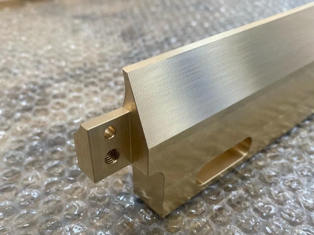
The as-machined finish is the surface state resulting directly from CNC processes, such as CNC milling and CNC turning, without additional surface treatments. It typically achieves a surface roughness of Ra 1.6–3.2 μm, providing cost-effective dimensional accuracy and functional performance. This finish is particularly suited to industries where mechanical precision and efficiency are prioritized, including automotive, robotics, aerospace, and general industrial equipment manufacturing.
Ideal for machining metals like aluminum and stainless steel and engineering plastics like PEEK, the machined finish excels in fabricating complex CNC geometries. Components featuring internal threads, deep cavities, thin walls, or precise bores benefit significantly from this approach, as it streamlines production, reduces lead times, and eliminates extra processing steps. Consequently, manufacturers can efficiently produce high-performance, precisely engineered components designed to withstand rigorous operational conditions.
The As Machined Finish: What It Is and When to Use It in CNC Machining Components
Scientific Principles & Industrial Standards
Definition:
The "as machined" surface finish refers to the surface condition produced directly from CNC machining processes, such as milling, turning, drilling, or boring. The resultant surface typically exhibits approximately Ra 1.6–3.2 μm controlled roughness levels.
Governing Standards:
ISO 1302: Geometrical product specification for surface texture
ASME B46.1: Surface texture standards, including roughness and waviness
ASTM A480/A480M: Standard practice for general surface finish on stainless steel products
Process Function and Cases
Performance Dimension | Technical Parameters | Application Cases |
|---|---|---|
Dimensional Precision | ±0.005 mm machining tolerance | Hydraulic valve bodies, precision fixtures, aerospace brackets |
Cost Efficiency | Reduces secondary finishing, saving 20–30% overall | Industrial component housings, automotive brackets |
Functional Adequacy | Surface roughness Ra 1.6–3.2 μm | Sealing surfaces, valve seats, flange faces |
Rapid Production | No secondary finishing required | Rapid prototyping, tooling inserts, emergency replacements |
Surface Finish Classification
Technical Specification Matrix
Machining Method | Key Parameters & Metrics | Advantages | Limitations |
|---|---|---|---|
Ra: 1.6–3.2 μm; Flatness ±0.02 mm | High accuracy, versatile geometries | Visible machining marks | |
Ra: 0.8–3.2 μm; Cylindricity ±0.01 mm | Precise cylindrical geometries | Limited to rotational symmetry | |
Ra: 1.6–6.3 μm; Hole tolerance ±0.02 mm | Fast hole formation | Rougher surfaces in deep holes | |
Ra: 0.8–1.6 μm; Bore tolerance ±0.005 mm | Precise internal diameters | Requires careful tool setup | |
Ra: 0.2–0.8 μm; Dimensional tolerance ±0.002 mm | Exceptional finish accuracy, low roughness | Slower process, higher cost |
Selection Criteria & Optimization Guidelines
CNC Milling
Selection Criteria: Optimal for intricate or flat components demanding tight dimensional accuracy with acceptable tooling marks.
Optimization Guidelines: Select carbide tools; set spindle speeds between 6,000–12,000 rpm; employ finishing passes with reduced feeds (0.05–0.1 mm/rev).
CNC Turning
Selection Criteria: Suitable for cylindrical components requiring tight tolerances and moderate surface finishes.
Optimization Guidelines: Use polycrystalline diamond (PCD) inserts for non-ferrous metals; optimize cutting speeds (250–500 m/min) for steels; ensure coolant delivery for thermal control.
CNC Drilling
Selection Criteria: Effective for general-purpose holes where moderate accuracy and surface finish are sufficient.
Optimization Guidelines: Apply coolant-through drills for depths greater than 5x diameter; use intermittent peck-drilling cycles to manage chips and improve surface quality.
CNC Boring
Selection Criteria: Preferred for precision bores demanding tight diameter control and improved surface smoothness (Ra 0.8–1.6 μm).
Optimization Guidelines: Control boring bar length-to-diameter ratio (<4) to minimize vibration; use consistent speeds (150–300 m/min); perform finishing passes at lower feed rates (0.02 mm/rev).
Material-Finish Compatibility Chart
Substrate | Recommended Machining Method | Performance Gain | Industrial Validation Data |
|---|---|---|---|
CNC Milling | Dimensional accuracy ±0.01 mm; Yield strength ~276 MPa | Aerospace structural parts per AMS QQ-A-225/8 | |
CNC Turning | Surface finish Ra 1.6 μm; Corrosion-resistant per ASTM A276 | Validated for chemical pumps in petrochemical plants | |
CNC Boring | Bore accuracy ±0.005 mm; Tensile strength 950 MPa | Aerospace hydraulic cylinders per AMS 4928 standards | |
CNC Milling | Consistent finish Ra 1.6 μm; Thermal stability up to 260°C | Medical implants per ISO 10993 and electronic housings | |
CNC Turning | Enhanced electrical conductivity ≥99.9% IACS | Precision electrical connectors meeting ASTM B187 |
As Machined Process Control: Critical Steps & Standards
Pre-Machining Essentials
Material Inspection: Verify dimensional tolerances within +0.1/-0 mm (ISO 2768-m standard compliance).
Tool Calibration: Ensure tool run-out within ≤5 μm accuracy (DIN 69871 standards).
Workpiece Clamping: Fixture setup achieving ±0.01 mm positioning accuracy verified by CNC probing.
Machining Process Controls
Surface Roughness Control: Periodic checks using a profilometer at ±0.1 μm resolution (ISO 4287).
Dimensional Control: Real-time CNC machine probing to verify dimensional accuracy ±0.005 mm.
Thermal Management: Coolant temperature consistently controlled within ±2°C to avoid thermal deformation.
Post-Machining Checks
Cleaning and Deburring: Ultrasonic cleaning at 40 kHz frequency, visually inspected under microscopy.
Inspection and Packaging: Comprehensive quality check with coordinate measuring machine (CMM accuracy ±2 μm), conforming to AS9100 standards.
FAQs
What surface roughness (Ra) can I expect from an as machined finish, and how consistent is it?
How does the cost of an as machined finish compare to polished, anodized, or coated surfaces?
Can the as machined finish meet sealing and pressure-holding requirements for precision components?
What types of materials perform best with an as machined finish?
Under what conditions should I consider additional surface treatments beyond the as machined state?