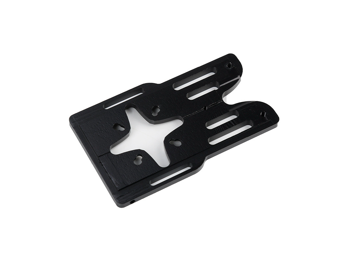
Ceramics in Aerospace: Exploring the Benefits of Multi-Axis CNC Machining for Lightweight Parts
Revolutionizing Aerospace with Advanced Ceramics
Modern aerospace systems demand materials that combine extreme heat resistance, lightweight properties, and structural stability. Ceramic components, now constituting 15-20% of next-gen aircraft engines, offer 60% weight reduction versus superalloys while withstanding temperatures exceeding 1,600°C. Through multi-axis CNC machining services, manufacturers achieve ±0.003mm tolerances in complex ceramic parts like turbine shrouds and radome panels.
The shift toward hypersonic platforms and reusable space vehicles has driven the adoption of silicon nitride and zirconia ceramics. These materials enable 30% fuel efficiency gains in jet engines while meeting MIL-STD-1942 thermal shock requirements.
Material Selection: Ceramic Solutions for Extreme Environments
Material | Key Metrics | Aerospace Applications | Limitations |
|---|---|---|---|
800 MPa flexural strength, 3.2 g/cm³ | Turbine blades, bearing races | Requires diamond tooling for machining | |
1,200 MPa compressive strength, 5.7 MPa√m fracture toughness | Thermal barrier coatings, sensor housings | Limited to <1,400°C in oxidizing environments | |
400 MPa flexural strength, 0.1 W/m·K thermal conductivity | Insulating spacers, antenna windows | Brittle fracture risk under impact | |
4.5 GPa hardness, 170 W/m·K thermal conductivity | Rocket nozzles, brake disks | High machining costs due to abrasiveness |
Material Selection Protocol
High-Temperature Engine Components
Technical Basis: Si₃N₄ (Grade SN-281) provides 1,200°C operational capability with 0.5% creep strain at 100MPa/100h. Post-machining laser surface glazing reduces surface roughness to Ra 0.05μm for reduced airflow turbulence.
Hypersonic Leading Edges
Scientific Rationale: C/SiC composites achieve zero ablation at Mach 7+ speeds when processed via 5-axis CNC with PCD tooling.
Radar-Transparent Structures
Design Strategy: Alumina-silica composites (ε<sub>r</sub>=3.2) enable 95% EM wave transmission for phased array radomes, machined to 0.1mm wall thickness.
Multi-Axis CNC Machining Optimization
Process | Technical Specifications | Aerospace Applications | Advantages |
|---|---|---|---|
0.001mm repeatability, 24,000 RPM spindle | Ceramic turbine blade cooling channels | Maintains 0.005mm wall uniformity | |
40kHz vibration, 0.02mm chip load | SiC nozzle throat sections | Reduces cutting forces by 60% | |
1,000W diode laser, 800°C localized heating | Zirconia thermal barrier coatings | Eliminates edge chipping | |
2μm diamond wheels, 0.2μm Ra | Bearing raceways | Achieves <0.1μm roundness error |
Process Strategy for Turbine Shroud Production
Green Machining
Stage: Machine 85% dense pre-sintered Si₃N₄ blanks with PCD end mills at 300 m/min
Precision: Achieve ±0.1mm oversize for sintering shrinkage compensation
Sintering
Protocol: 1,800°C/4h in nitrogen atmosphere to reach 99.3% theoretical density
Finish Machining
Technology: Ultrasonic-assisted 5-axis milling with 0.1mm DOC and cryogenic CO₂ cooling
Quality: Final dimensions ±0.003mm, surface roughness Ra 0.2μm
Surface Engineering: Enhancing Ceramic Performance
Treatment | Technical Parameters | Aerospace Benefits | Standards |
|---|---|---|---|
200μm thickness, 3,800 HV | Oxidation protection up to 1,650°C | MIL-C-83231 | |
50μm dimples, 30% surface coverage | Reduces aerodynamic drag by 12% | ASME B46.1 | |
YSZ coatings, 8% porosity | Thermal shock resistance improvement | ASTM C633 | |
HF:HNO₃ 3:1, 20μm removal | Removes machining-induced microcracks | ISO 14916 |
Coating Selection Logic
Re-entry Vehicle Nose Cones
Solution: CVD TaC/HfC multilayer coatings withstand 2,500°C plasma flows for 300+ seconds
Engine Combustor Liners
Technology: EB-PVD YSZ with columnar microstructure provides a 3,000-cycle thermal fatigue life
Quality Control: Aerospace-Grade Validation
Stage | Critical Parameters | Methodology | Equipment | Standards |
|---|---|---|---|---|
Density Verification | 99.5% theoretical density | Archimedes' principle | Mettler Toledo XS204 | ASTM B962 |
NDT | Detect ≥50μm flaws | Active thermography | FLIR X8500sc | NAS 410 Level III |
Dimensional Metrology | 0.001mm form tolerance | White-light interferometry | Zygo NewView 9000 | ASME Y14.5-2018 |
Thermal Testing | 1,500°C→25°C water quench x 50 cycles | Thermal shock resistance | Lenton tube furnace | MIL-STD-810H |
Certifications:
NADCAP AC7114/8 for non-metallic machining
AS9100D with ceramic-specific process controls
Industry Applications
Hypersonic Leading Edges: C/SiC panels with 5-axis machined cooling channels surviving Mach 8
Satellite Thrusters: Al₂O₃ nozzles achieving 0.005mm concentricity for ion beam focusing
Turbine Blades: Si₃N₄ components with CVD coatings enabling 1,800°C operation
Conclusion
Advanced ceramic CNC machining services enable 40-60% weight reduction in critical aerospace systems while meeting MIL-STD-2032 performance requirements. Integrated multi-axis solutions reduce ceramic component costs by 30% through near-net-shape manufacturing.
FAQ
Why ceramics outperform metals in turbine engines?
How to prevent ceramic cracking during machining?
What standards govern aerospace ceramics?
Can ceramics replace composites in re-entry vehicles?
How to inspect internal ceramic flaws?

