Custom Online Copper CNC Machining Service

Our Custom Online Copper CNC Machining Service offers precision machining for copper parts, ensuring high accuracy and quality. We handle complex designs with advanced CNC technology, providing fast turnaround times and custom solutions tailored to your project needs.
Send us your designs and specifications for a free quotation
All uploaded files are secure and confidential

Know About Copper CNC Machining

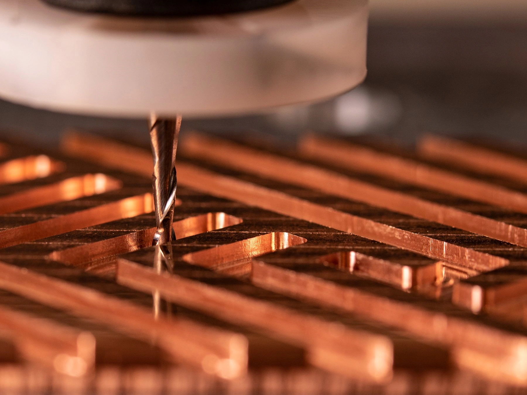
Copper CNC machining involves precision cutting and shaping of copper materials using advanced CNC technology. It offers excellent conductivity and machinability, ideal for electrical and thermal applications. Proper machining parameters and tool selection are essential for achieving high-quality, precise copper parts.
Know About Copper CNC Machining

Category

Description

Machining Properties

Copper is highly conductive and ductile, ideal for electrical and thermal applications. It’s soft and relatively easy to machine, but its high thermal conductivity can lead to tool wear. Copper alloys, such as bronze and brass, are often used for enhanced strength, corrosion resistance, and machinability. Surface finish can vary depending on the alloy used.

Machining Parameters

Optimal cutting speeds are essential when machining copper to minimize tool wear and achieve smooth finishes. For CNC milling, a speed of 100-200 SFM (surface feet per minute) is typical. Feed rates should be moderate to prevent tool deflection. Sharp tools, typically carbide or coated high-speed steel, handle copper's softness and prevent material buildup on the tool.

Precautions

Copper’s high thermal conductivity can cause rapid heat buildup, leading to tool wear. To combat this, use adequate coolant or lubrication to maintain tool life and surface finish. Prevent material work-hardening by avoiding excessive cutting forces and using proper feeds. Additionally, copper can be prone to tearing, so sharp tools and stable machining setups are crucial for quality results.

Typical CNC Machining Copper Alloys

Typical CNC machining copper alloys include Copper C101, C110, Beryllium Copper, and Brass. These alloys are chosen for their excellent electrical conductivity, corrosion resistance, and machinability. Common applications include electrical connectors, heat exchangers, industrial machinery, and aerospace components.

Copper Alloys

Tensile Strength
(MPa)

Yield Strength
(MPa)

Fatigue Strength
(MPa)

Elongation
(%)

Hardness
(HRC)

Density
(g/cm³)

Applications

Copper C101
(T2)

210–250

35–70

40–55

30–50

40–45

8.92

Electrical connectors, heat exchangers, electronic components

Copper C103
(T1)

230–280

45–90

50–65

30–45

45–50

8.96

Electrical conductors, power generation, bus bars

Copper C103
(TU2)

220–270

50–90

45–60

25–40

45–50

8.96

Conductors, heat exchangers, brazing

Copper C110
(TU0)

210–270

40–70

50–60

30–45

45–50

8.96

Electrical wiring, power generation, telecommunication

Beryllium Copper

690–1000

450–650

350–500

2–10

30–35

8.3

Aerospace, electrical contacts, tooling

Copper C102
(Oxygen-Free Copper)

250–300

60–90

50–65

25–45

45–50

8.96

High-end electronics, semiconductor manufacturing, welding

Copper C260
(Brass)

300–550

150–300

150–250

25–40

55–70

8.47

Plumbing fittings, electrical components, decorative hardware

Copper C194
(Alloy 194)

700–900

350–500

200–300

5–10

25–30

8.92

Electrical connectors, springs, high-performance components

Copper C175
(Chromium Copper)

550–700

250–400

300–400

5–10

35–40

8.9

Electrical contacts, tooling, aerospace components

Copper C330
(Leaded Copper)

250–350

70–150

100–150

25–40

40–55

8.55

Plumbing fittings, gears, electrical parts

Copper C151
(Tellurium Copper)

340–460

130–230

150–200

20–30

35–45

8.9

Electrical contacts, precision components, aerospace

Copper C172
(Beryllium Copper – High Strength)

1000–1200

700–900

500–700

3–6

35–45

8.3

Aerospace, electrical connectors, high-strength springs

Copper C194
(High Strength Copper)

800–1000

350–550

250–350

5–10

25–30

8.92

Electrical connectors, power distribution, military applications

Copper C510
(Phosphor Bronze)

600–800

250–400

200–300

10–25

35–50

8.8

Electrical contacts, springs, bearings

Copper C521
(Leaded Phosphor Bronze)

600–750

250–400

200–300

5–10

40–55

8.8

Electrical connectors, bearings, industrial components

Copper C120
(Electrolytic Tough Pitch Copper)

210–270

60–90

50–60

30–45

40–45

8.96

Power generation, electrical wiring, telecommunications

Copper C630
(Aluminum Bronze)

800–1000

400–600

300–450

10–15

40–50

8.9

Marine hardware, aerospace, industrial machinery

Copper C905
(Silicon Bronze)

600–800

250–400

200–300

10–25

40–50

8.8

Marine applications, turbine blades, industrial components

Copper C706
(Nickel Silver)

400–600

150–300

150–200

20–35

35–45

8.7

Musical instruments, jewelry, decorative hardware

Copper C482
(Copper Nickel)

550–750

250–400

200–300

15–25

35–45

8.9

Marine applications, heat exchangers, desalination plants

Surface Treatment For CNC Machined Copper Parts

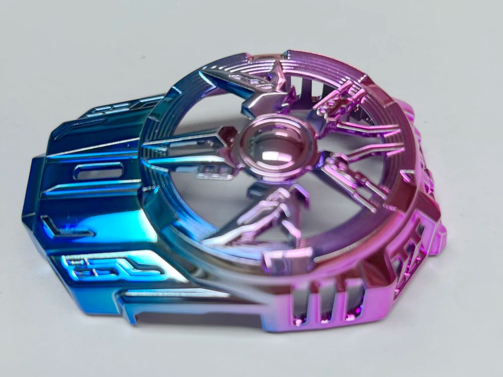
Surface treatment for CNC machined copper parts includes processes like electroplating, anodizing, passivation, and polishing. These treatments enhance corrosion resistance, improve durability, and provide a smooth finish. They are commonly used in electronics, aerospace, and automotive applications to ensure optimal performance.

CNC Machined Copper Parts Gallery

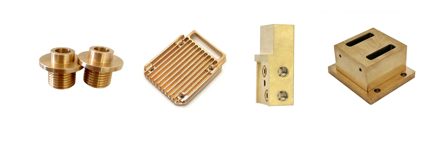
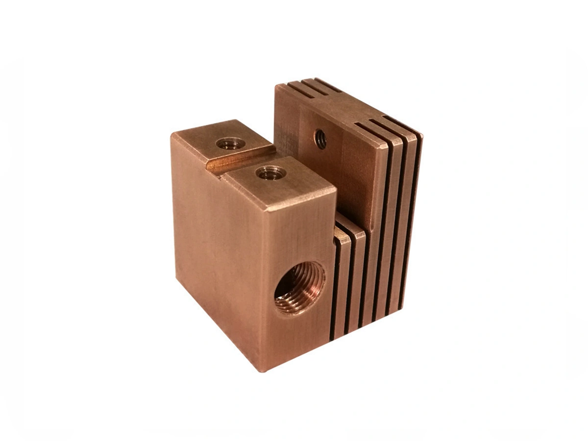
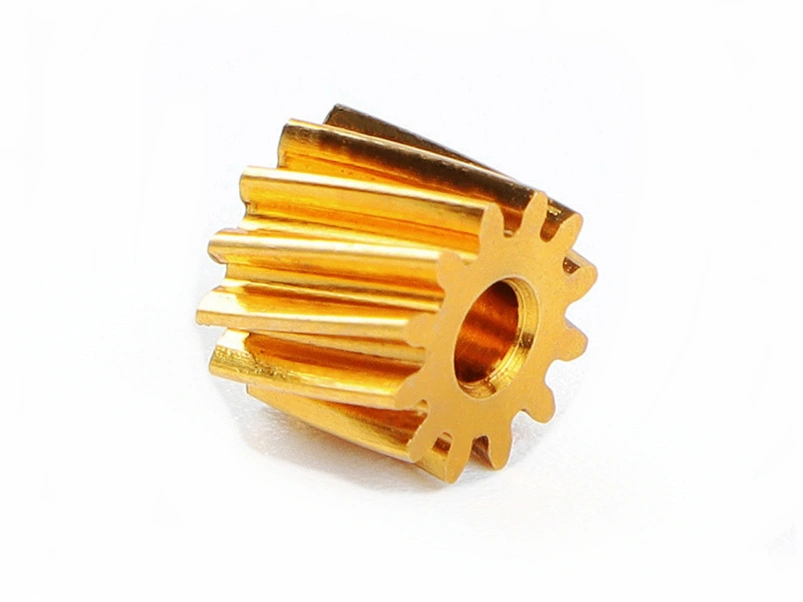
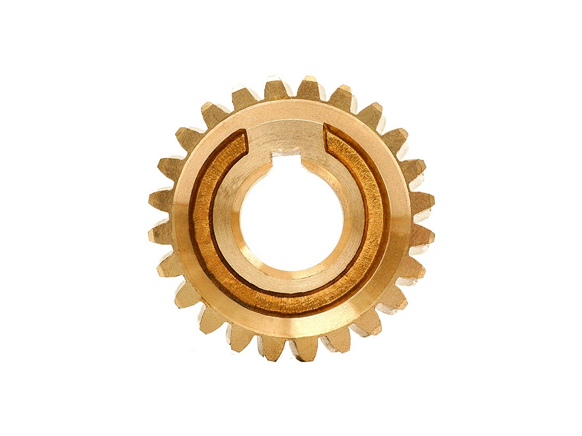
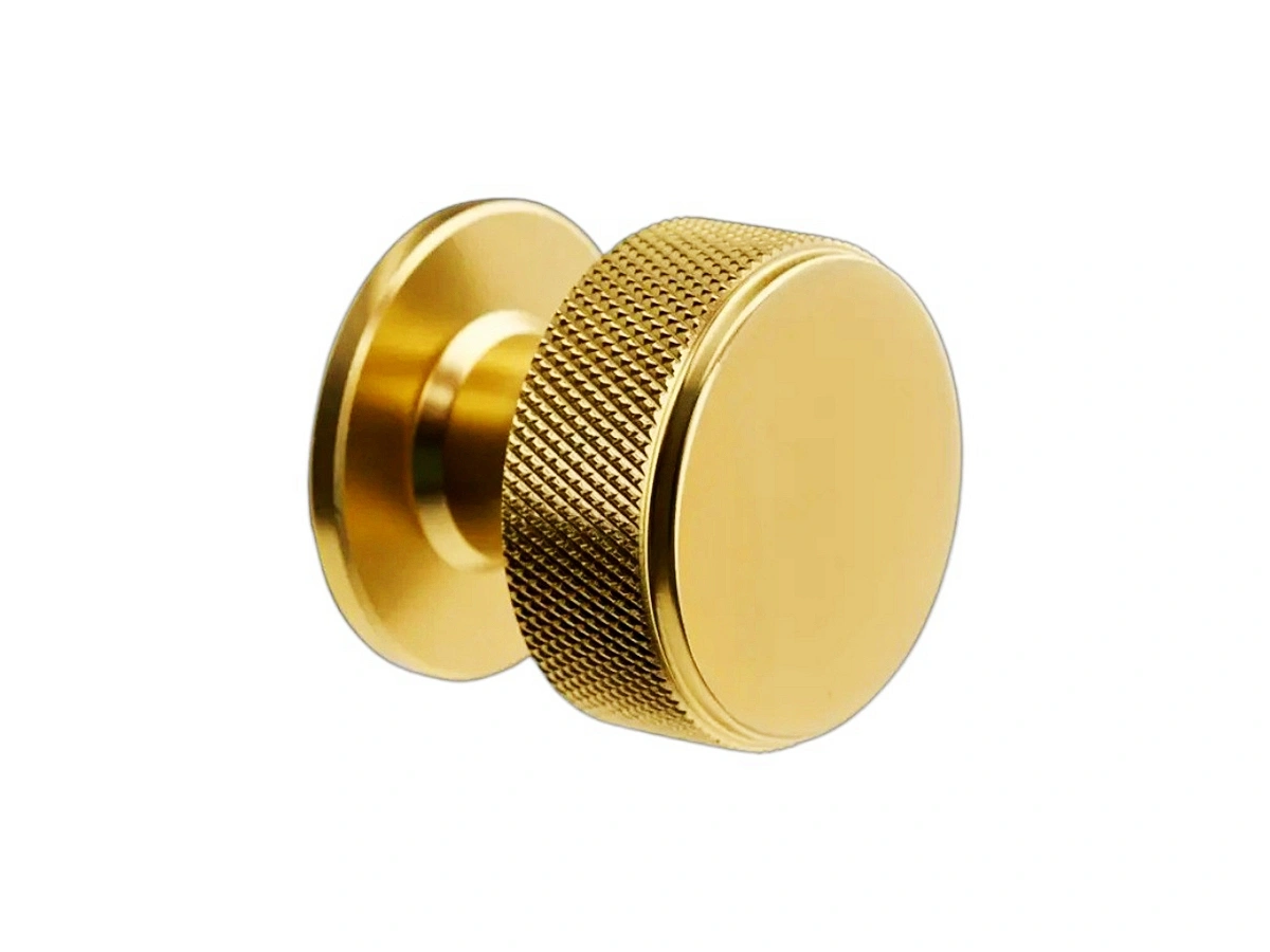
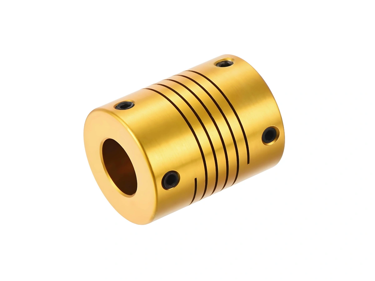
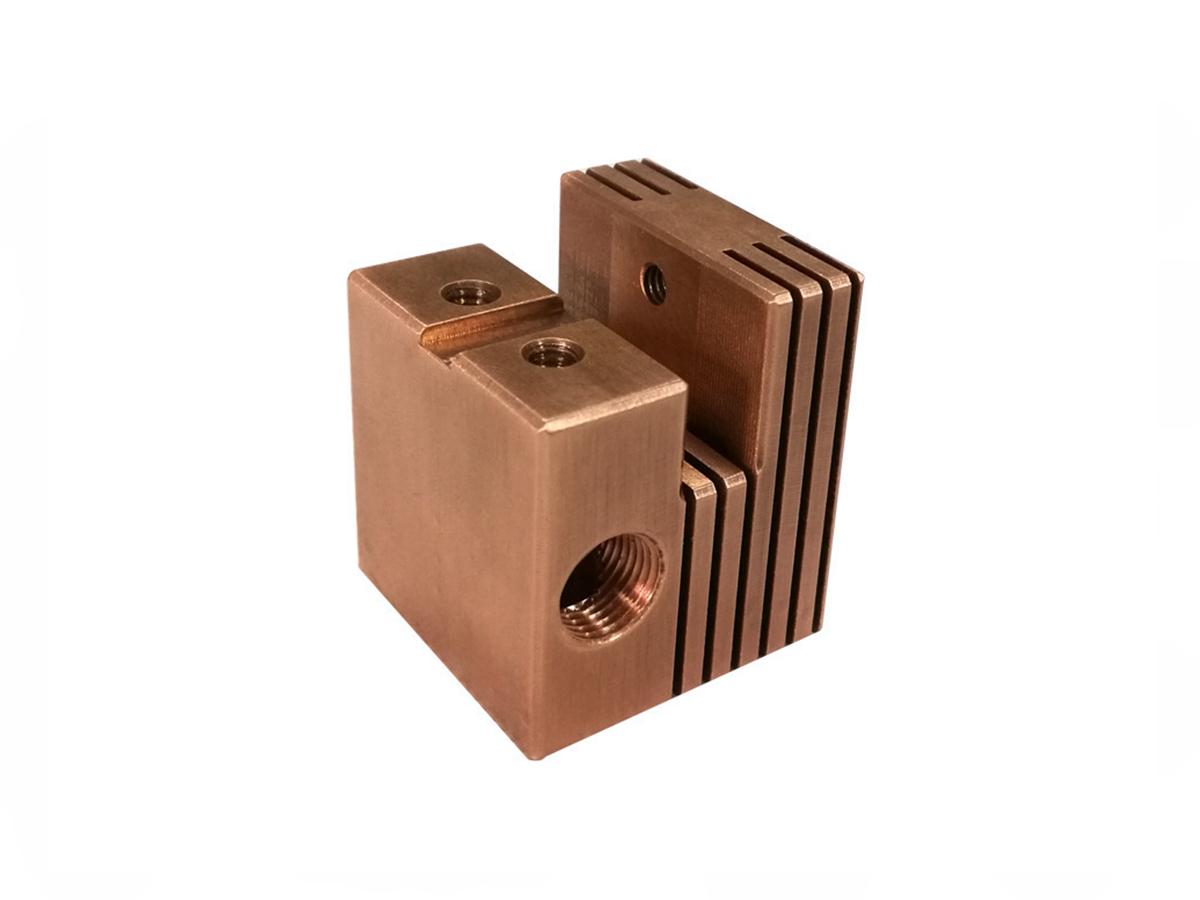
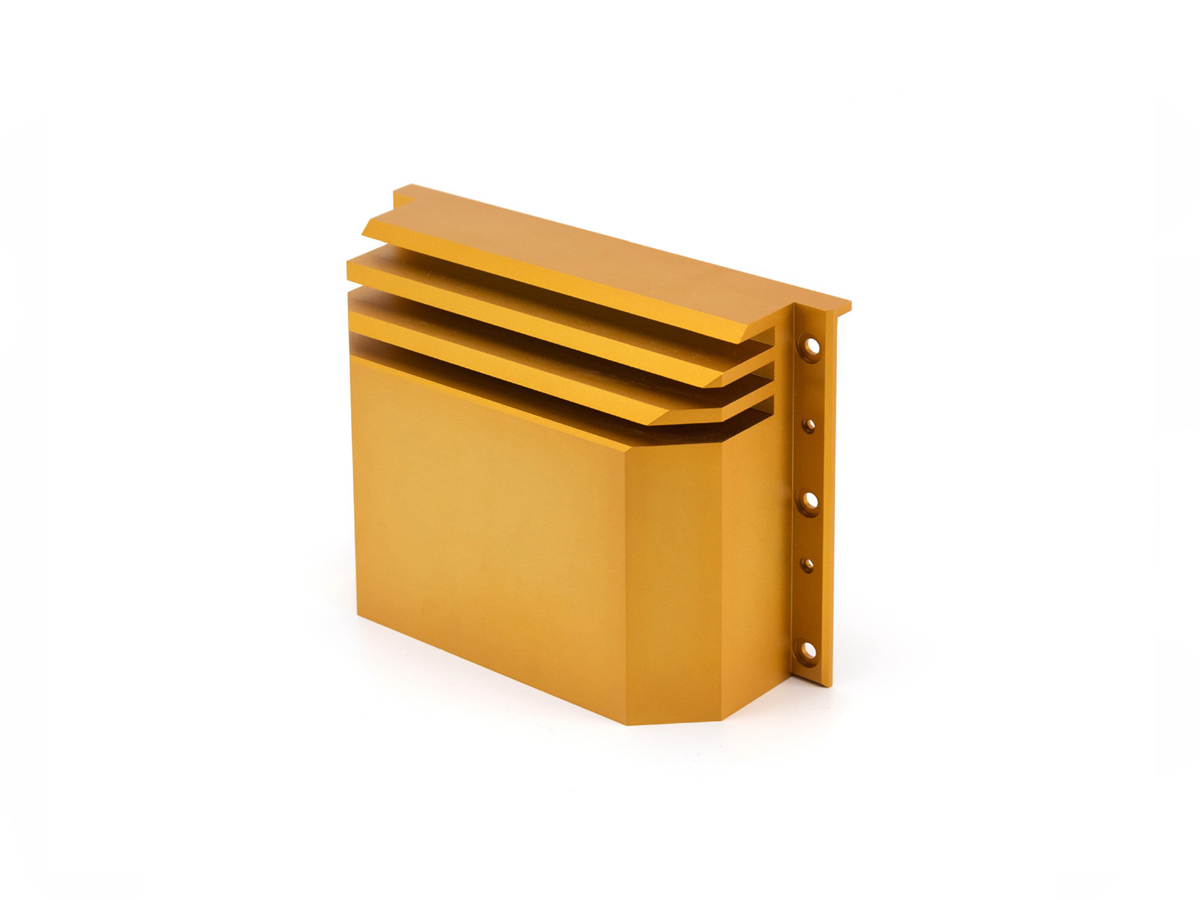
Explore our CNC machined copper parts gallery, showcasing high-precision components made from top-grade copper alloys. From electrical connectors to aerospace parts, our gallery highlights the versatility and quality of our custom copper machining solutions for diverse industries.
Let's Start A New Project Today

Copper Alloy CNC Machining Parameter Suggestion

Copper alloy CNC machining requires optimized parameters for efficiency and quality. Key factors include spindle speed, cutting depth, feed rate, coolant type, and tool material. Proper adjustments ensure smooth machining, minimize tool wear, and achieve precise, high-quality copper components.

Parameters

Recommended Range/Value

Explanation

Spindle Power

3-7 kW

High spindle power ensures smooth cutting, minimizes tool wear, and maintains consistency when machining copper alloys, which are prone to galling and heat buildup.

Spindle Speed

800-2500 RPM

Copper alloys require high spindle speeds to efficiently remove material while preventing overheating and oxidation, ensuring a clean, smooth finish.

Cutting Speed

150-300 m/min

Copper alloys have good thermal conductivity, requiring high cutting speeds to minimize heat accumulation and prevent material deformation.

Feed Rate

0.05-0.2 mm/tooth

Higher feed rates help achieve faster material removal while maintaining surface finish quality and reducing tool wear.

Deep Cut

1-5 mm

Shallow cuts are recommended for copper alloys to avoid heat buildup and tool damage. However, deeper cuts may be used when appropriate for specific features.

Cutting Depth

0.1-0.5 mm

Shallow cuts are ideal for better control, precision, and to avoid the risk of workpiece deformation or tool wear.

Pitch

0.2-1.0 mm

Using a consistent pitch helps maintain an even cutting process, ensuring uniform material removal while preventing tool clogging.

Coolant Type

Flood coolant or air

Copper alloys are sensitive to overheating, so using flood coolant or compressed air helps to dissipate heat, reduce tool wear, and improve surface finish.

Tool Material

Carbide, High-Speed Steel

Carbide tools are ideal for copper alloys due to their high wear resistance and ability to maintain sharp edges during high-speed machining.

Tool Geometry

Sharp tools with a low rake angle

A low rake angle helps to prevent material adhesion (galling) and ensures better control during the cutting process, as copper is a sticky material.

Tool Wear Monitoring

Essential

Copper alloys can cause rapid tool wear due to their high thermal conductivity, so monitoring tool wear is important to maintain part quality and consistency.

Cutting Fluid Pressure

40-60 bar

High-pressure coolant ensures effective chip removal, cooling, and lubrication, reducing the risk of clogging or material buildup, improving surface finish.

Chip Removal Rate

0.5-2 mm³/min

A high chip removal rate helps clear material quickly and reduces the chance of tool damage or part deformation.

Surface Finish

Ra 0.8-1.6 µm

Achieving a fine surface finish is essential in copper machining, especially for electrical or high-precision components, to reduce friction and enhance performance.

Tool Path Strategy

Adaptive, Contour

Adaptive tool paths allow efficient material removal, while contour paths help achieve smooth, accurate contours, crucial for copper alloy parts requiring tight tolerances.

Tolerance Suggestions for Copper CNC Machining

Tolerance suggestions for copper CNC machining ensure precision and functionality in parts. General tolerances like ±0.1 mm are standard, while tighter precision tolerances, wall thickness, and part size considerations ensure quality. These guidelines optimize machining, reducing tool wear and enhancing product consistency.

Tolerance Type

Recommended Range/Value

Explanation

General Tolerances

±0.1 mm

Standard machining tolerance for copper allows for typical part fits without requiring advanced precision.

Precision Tolerances

±0.05 mm

Precision tolerances ensure high-quality parts, necessary for critical applications such as electrical components.

Min Wall Thickness

0.5-1.0 mm

Thin walls risk deformation and may cause difficulty in machining, so a minimum thickness ensures stability.

Min Drill Size

0.5 mm

Copper alloys are soft and can deform, so small drill sizes (down to 0.5mm) are achievable without excessive tool wear.

Maximum Part Size

500 mm x 500 mm

Larger parts may experience tool flexing or machining inaccuracies, limiting size for precision.

Minimum Part Size

5 mm x 5 mm

Parts below this size may be difficult to handle during machining due to rigidity and tool engagement limitations.

Production Volume (Low)

50-500 units

Low-volume runs require less specialized tooling and shorter lead times, ideal for initial tests and prototypes.

Production Volume (High)

500-10,000+ units

High-volume production allows for optimized machining time, reduced costs, and efficient tool usage.

Prototyping Lead Time

2-5 days

Prototyping of copper parts can be completed quickly with standard machining processes to verify design.

Low Volume Lead Time

5-10 days

Low-volume copper machining requires some setup time but remains relatively quick for custom orders.

High Volume Lead Time

10-30 days

High-volume production requires optimized planning and may need additional tooling and setup time for consistency.

Surface Finish (Ra)

Ra 0.8-1.6 µm

Achieving fine surface finishes is critical for copper components used in electrical, automotive, and aerospace industries.

Frequently Asked Questions

Explore Related Resources

Copyright © 2025 Machining Precision Works Ltd.All Rights Reserved.