Precision Electrical Discharge Machining (EDM) Service
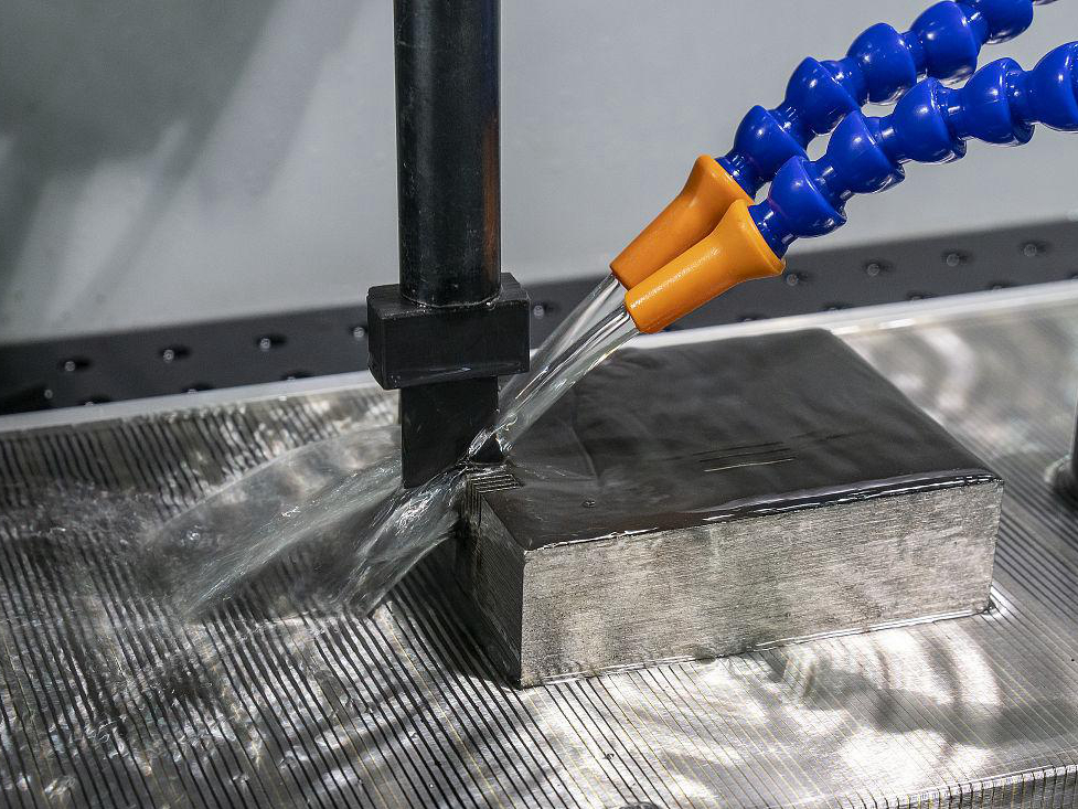
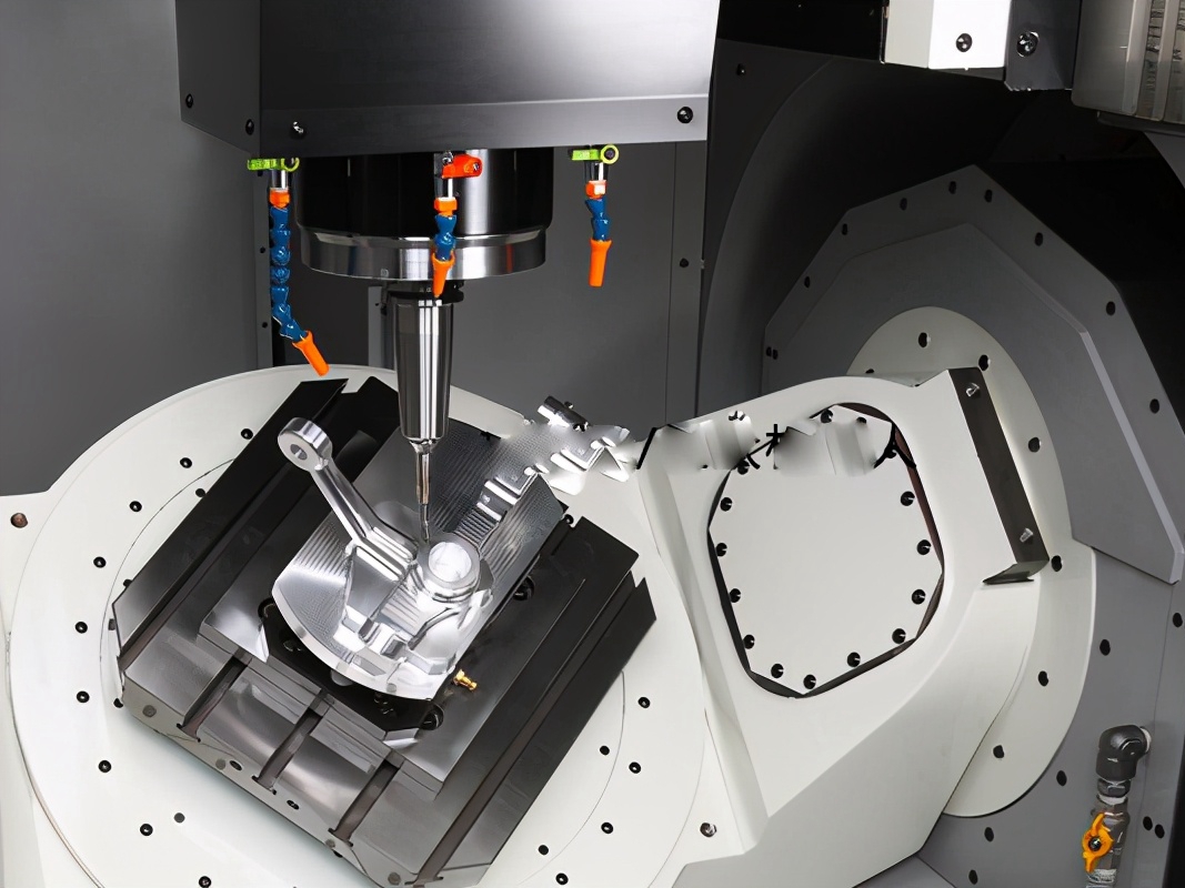
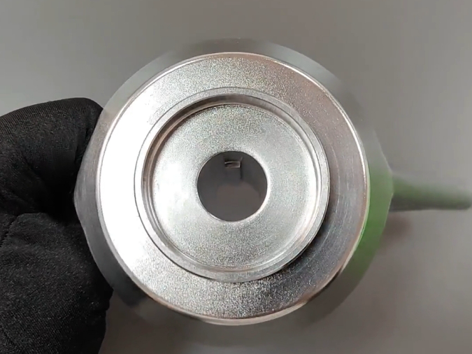
Precision Electrical Discharge Machining (EDM) service utilizes controlled electrical sparks to precisely machine hard materials and complex shapes. Ideal for intricate designs, tight tolerances, and difficult-to-machine materials, EDM ensures high accuracy, smooth finishes, and minimal material deformation in manufacturing.
Send us your designs and specifications for a free quotation
All uploaded files are secure and confidential
Electrical Discharge Machining (EDM) Applications
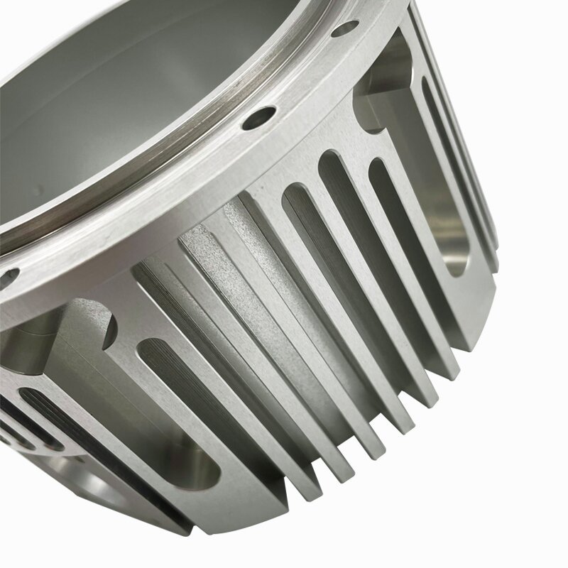
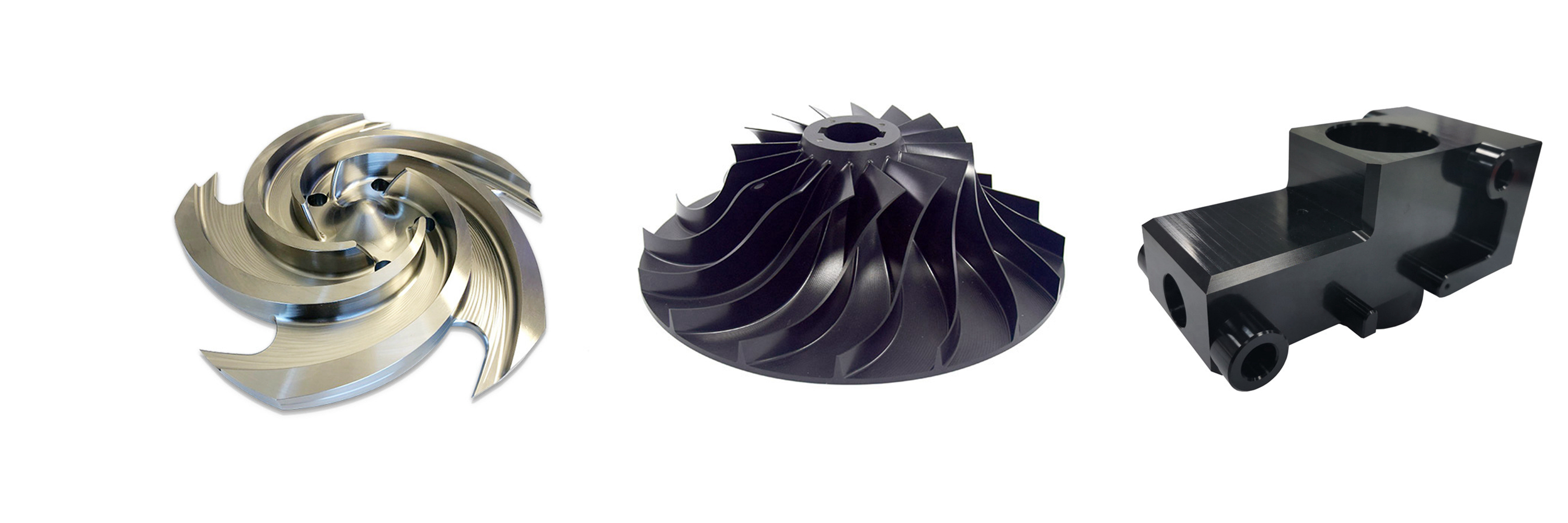
Precision Electrical Discharge Machining (EDM) applications involve creating intricate, high-precision components by eroding hard materials with electrical sparks. Ideal for complex shapes, tight tolerances, and tough materials, EDM is widely used in aerospace, medical, automotive, and tooling industries.
Electrical Discharge Machining Materials
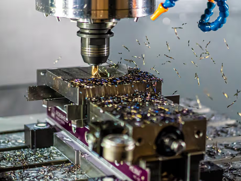
Electrical Discharge Machining (EDM) is used to precisely shape hard materials like superalloys, titanium, and stainless steel. It’s also effective for machining conductive metals such as aluminum, copper, brass, and bronze. EDM can process a variety of materials, including carbon steel, plastics, and ceramics, offering versatility in manufacturing complex components with high precision and minimal material stress.
Surface Treatment for EDM Parts
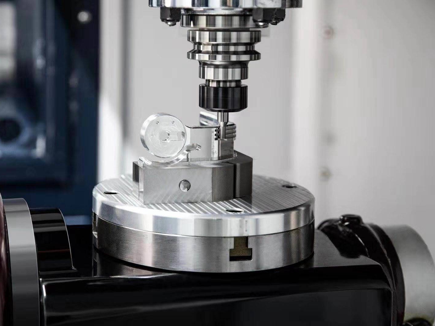
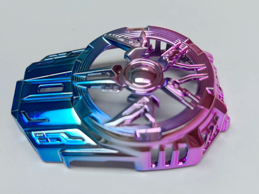
Surface treatment for EDM parts enhances durability, corrosion resistance, and appearance. Techniques like polishing, coating, and nitriding improve the surface integrity, reduce wear, and extend the lifespan of EDM-manufactured components, ensuring optimal performance in demanding industrial applications.
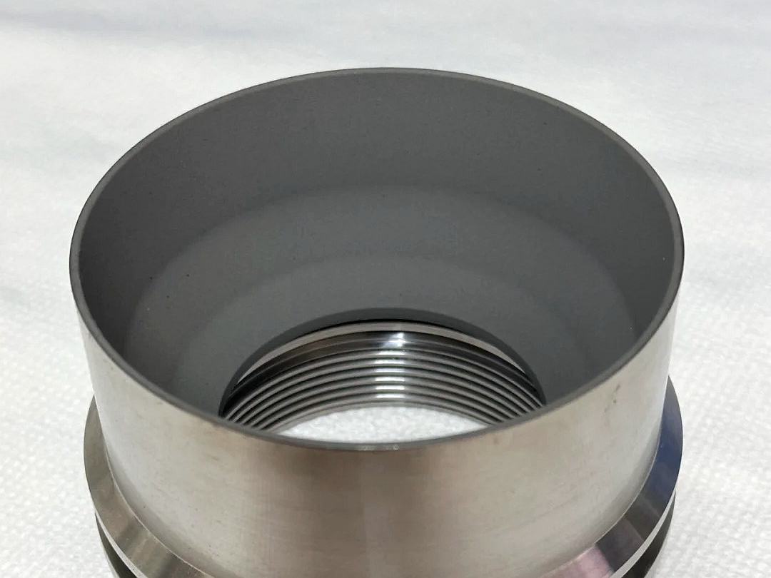
learn more
Thermal Coating
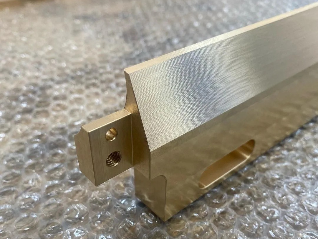
learn more
As Machined
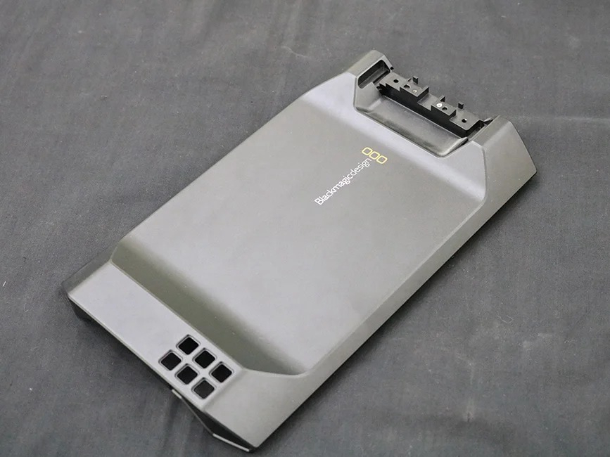
learn more
Painting
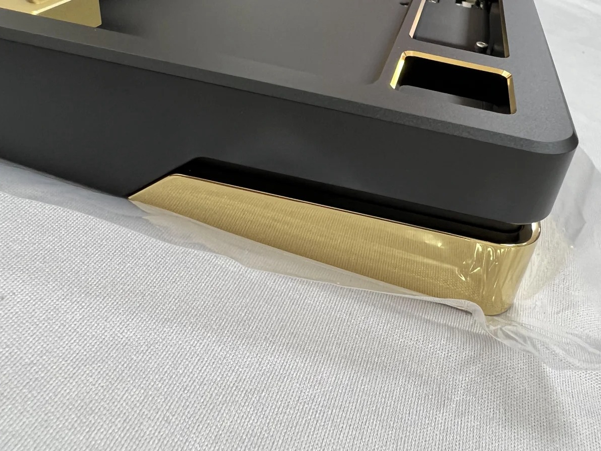
learn more
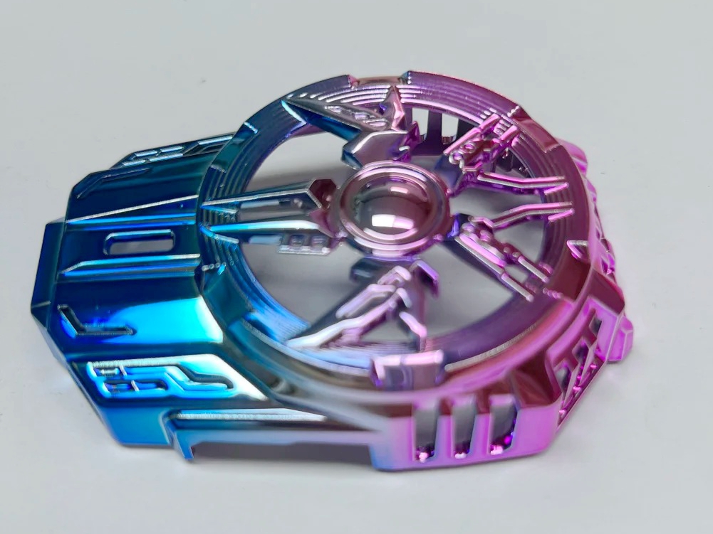
PVD (Physical Vapor Deposition)
learn more
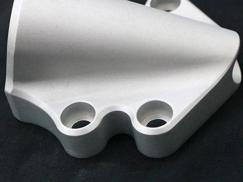
Sandblasting
learn more
Electroplating

learn more
Polishing
learn more
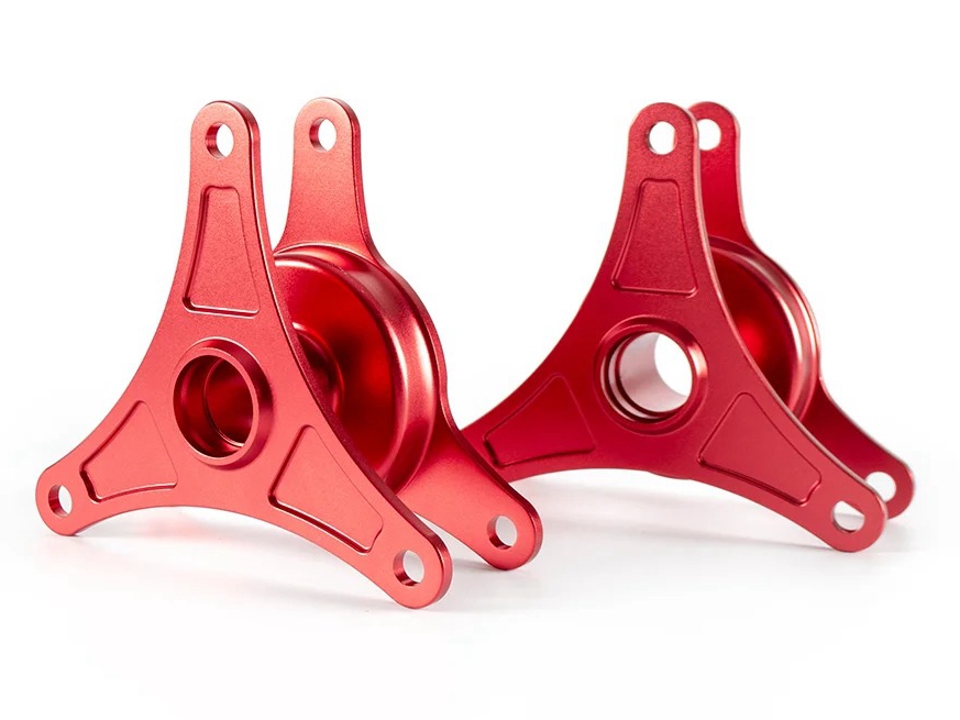
Anodizing
learn more
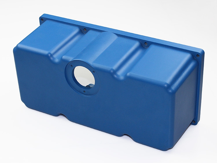
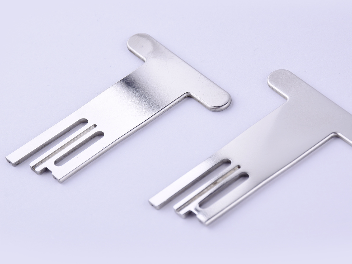
Powder Coating
learn more
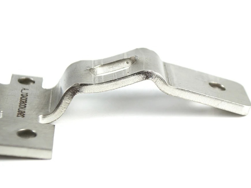
Electropolishing
learn more
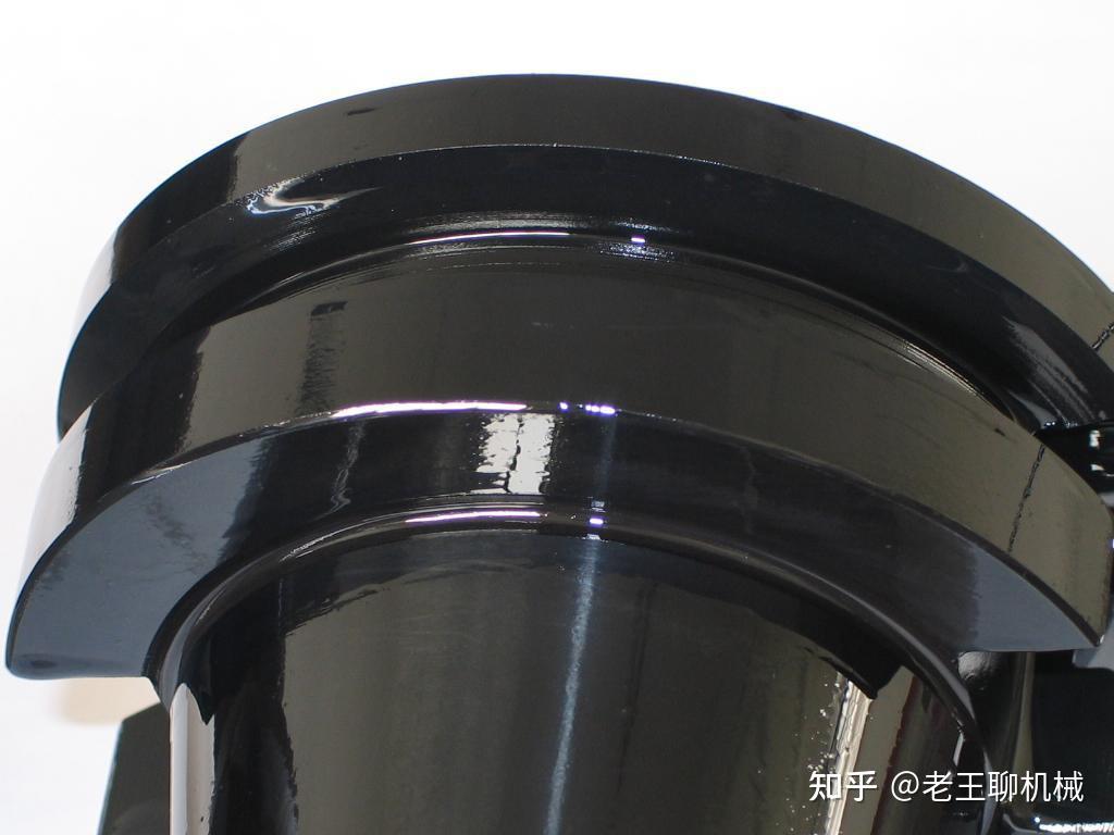
Passivation
learn more
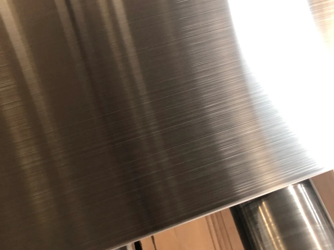
Brushing
learn more
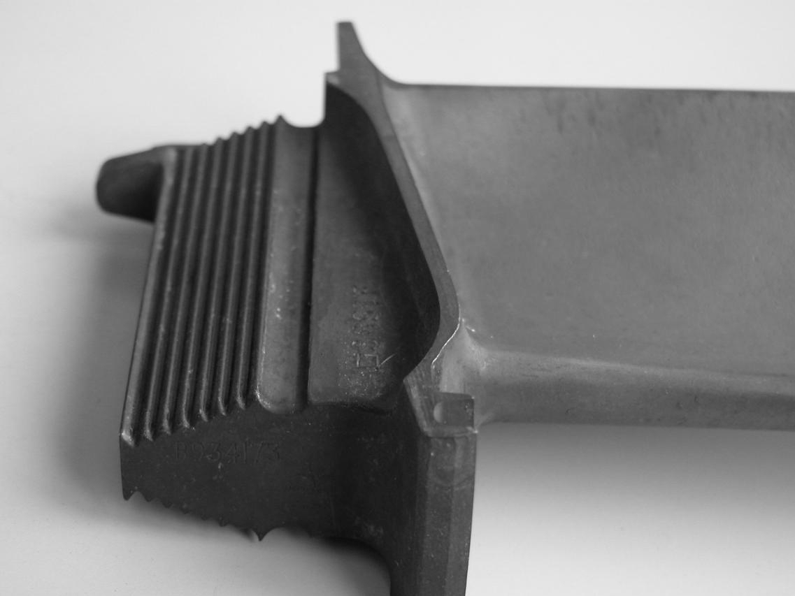
Black Oxide
learn more
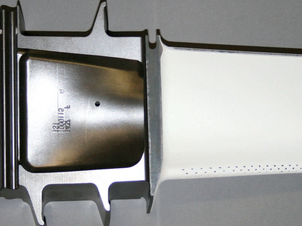
Heat Treatment
learn more
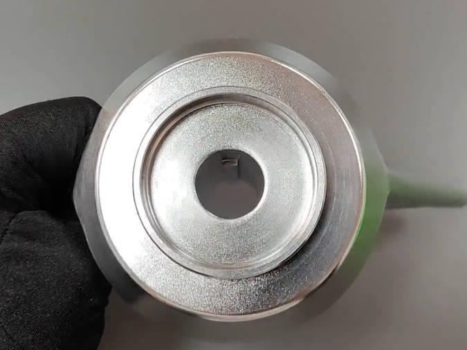
Thermal Barrier Coating (TBC)
learn more
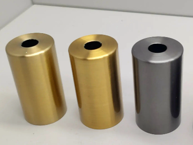
Tumbling
learn more
Alodine
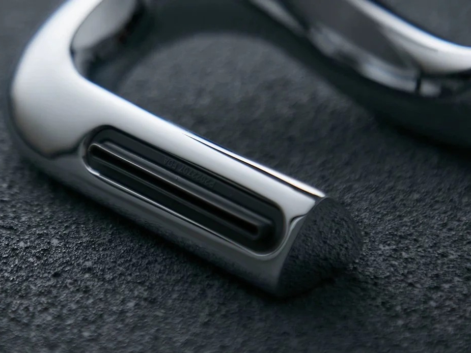
learn more
Chrome Plating
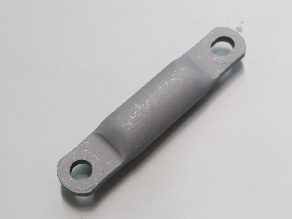
learn more
Phosphating
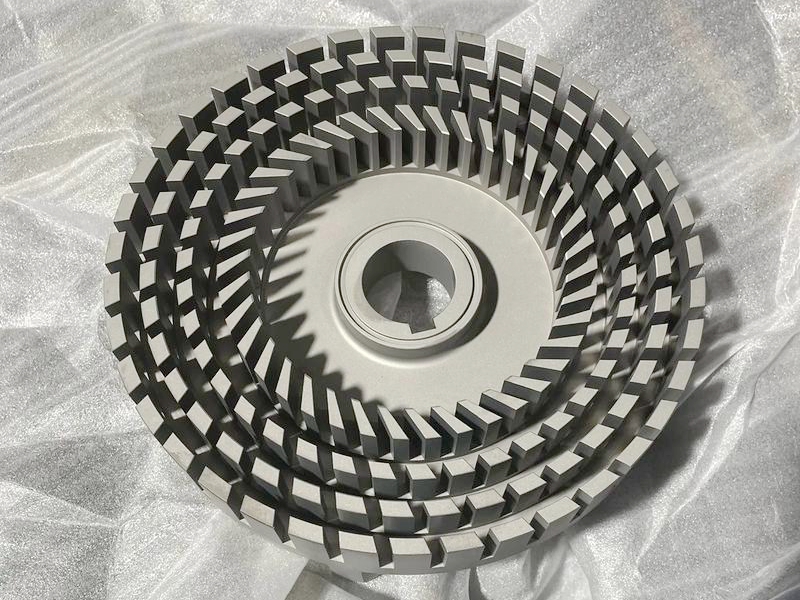
learn more
Nitriding
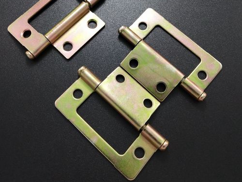
learn more
Galvanizing
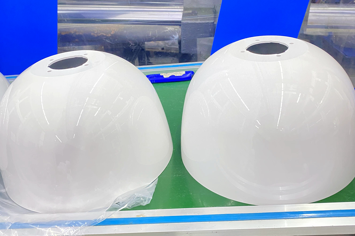
learn more
UV Coating
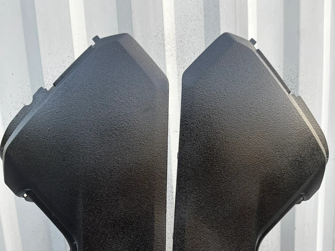
learn more
Lacquer Coating
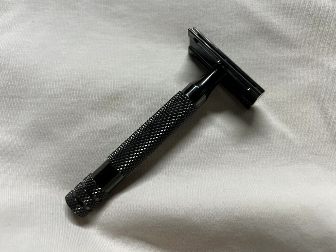
learn more
Teflon Coating
Let's Start A New Project Today
EDM Machining Tolerance Suggestions
EDM machining tolerance suggestions provide guidance for achieving high precision in complex components. By selecting appropriate tolerances—such as ±0.1 mm for general use and ±0.005 mm for high-precision parts—manufacturers can optimize performance, minimize errors, and meet stringent design requirements.
EDM Machining Design Guideline
EDM machining design guidelines ensure efficient and accurate production of complex parts. By considering factors like electrode design, radii, hole placement, surface finish, and tolerance, manufacturers can achieve optimal results, reduce tool wear, and meet high-precision requirements effectively.
